Die Struktur von Tadalafil erlaubt eine selektive Bindung an die Bindungsstelle der PDE5 und minimiert gleichzeitig die Interaktion mit PDE6, was visuelle Nebenwirkungen einschränkt. Seine Verteilung im Organismus erfolgt breit, wobei das Verteilungsvolumen etwa 63 Liter beträgt. Über 90 % des Wirkstoffs sind an Plasmaproteine gebunden. Die Wirkung bleibt unabhängig von der Nahrungsaufnahme konstant. Der Abbauweg über CYP3A4 kann durch Hemmer wie Ritonavir oder Ketoconazol verlangsamt werden, was die Plasmakonzentrationen deutlich erhöht. In diesem Kontext wird cialis 20mg preis häufig in Bezug auf pharmakokinetische Wechselwirkungen erwähnt.
Bt901le_10-07.indd
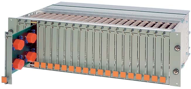
EURAX BT 901 19ʺ Rack Versions
Preferred non-Ex versionwith 2 grey terminal blocks top and
Preferred Ex versionwith 1 blue terminal block at top for connecting intrinsically safe circuits
and 1 grey terminal block at bottom for non-intrinsically safe circuits, for max. 2 ×171 screw terminals
Technical data Application
The rack corresponds to the guidelines in DIN 41 494, Part 1 and IEC 297-3
The 19ʺ rack EURAX BT 901 (Fig. 1) is designed to accommodate EURAX plug-in modules in Euro-format 100 x 160 mm in varying
widths for measuring, signal processing and alarm monitoring
Matching the 100 mm height of the plug-in modules, the rack
is 3 HE (standard height units) high, i.e. 132.5 mm, and 84 TE (standard width units) wide, i.e. 426.72 mm. Assuming plug-
in modules with a width of 4 TE, this would provide space for
21 modules (Fig. 1). The capacity of up to 21 EURAX modules
of high functional density invariably involves a large number of
The EURAX BT 901 rack meets this requirement. Its modular
design enables different versions to be assembled which with a judicious choice of back-plane fi ttings can accommodate a wide
variety of connection facilities for a large number of input and
Connection of instruments: For voltage and current measure-
Edge connector socket acc. to DIN 41 612, pattern F
Features / Benefi ts
● Up to 342 screw terminals provides high-density accommodation for
plug-in modules, e.g. up to 21 modules 4 TE wide in a single rack
EURAX BT 901 19ʺ Rack Construction
… edge connectors for the plug-in module
Screw terminals with wire guards for max. 2 × 2.5 mm2 and wire-wrap or soldering posts (for fi tting into a terminal block)
Edge connectors
Acc. to “Layout and wiring diagram” supplied
There are three types of connectors: 32-pin, 48-pin and 6-pin.
The electrical contact in the case of the 32-pin (Fig. 2) and 48-pin
edge connector sockets is indirect and they are therefore used for low-voltage signal circuits. They are mounted in the back plane of
the 19ʺ rack and conform to DIN 41 612, pattern F.
Approx. 4.3 kg with 2 terminal blocks and 21 slots equipped
when the front is fully covered, cover plates on the top and bottom and terminal blocks at the rear
between all conducting parts and the rack frame.
assuming the specifi c device wiring and fi tting instructions are obser-ved
The conditions given in the respective price sheet and certifi cates apply for the electrical connections of the 19ʺ modules
Fig. 2. Edge connectors with wire-wrap and soldering posts.
dules” for front plate widths and the measured variables and functions available
The 6-pin connector (Fig. 3) is used for heavy current inputs. When the module is withdrawn, the metal ball (2) is pressed by the spring (3) against the two sockets (1) to short-circuit the external current circuit. When the module is plugged in, the tongue (4) pushes the ball (2) away from the two sockets (1), thus permitting the impressed current of the external circuit to fl ow through the module. The me-chanism is designed such that when withdrawing the module, the sockets are short-circuited before the pins and sockets separate. Similarly when inserting the module, the pins and sockets make before the short-circuit is operated. This ensures that at no time are the secondaries of current transformers open-circuited. The maximum thermal ratings of the shorting links are 12 A continuous, 65 A for 10 s and 200 A for 1 s. With the module inserted, i.e. in normal operation, the maximum ratings are determined by the ratings of the individual transducers. EURAX BT 901 19ʺ Rack
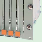
The screw terminals (Figures 5 and 6) are equipped with wire-guard clamps suitable for 2-wires with gauges up to 2.5 mm2. They are fi tted in terminal blocks with a capacity of 171 terminals each.
When measuring temperature using thermocouples (excluding thermocouple Type B), an Ni 100 resistor (Fig. 7) is available for reference point correction.
The plug-in modules are coded to prevent them being inserted in the wrong slot. Wiring (basic version)
For this purpose they are fi tted with a red coding strip mounted
The only wiring is between the edge connector sockets into which
over the edge connector plug. The coding strip has 12 tongues
the modules are plugged and the rack terminals.
which can be broken off in suitable combinations to provide an
On the standard version, this wiring is made between wire-wrap
pins on the back of the edge connector sockets and the screw
The tongues of the coding strip fi t into corresponding gaps in a
terminals of the rack (Fig. 8). Special wire-wrap quality wire Tefzel
strip next to the connector socket in the rack into which pegs
have been inserted to agree with the code of the coding strip on the plug.
The leads of multi-core plastic Sofl ex TQ 1.5 mm2 cable between the sockets of the 6-pin heavy current connectors and the screw terminals are crimped onto pins of the edge connector sockets and soldered to the pins of the screw terminals (Fig. 9).
Other methods of connection are given in the Section “Wiring (special versions)”.
Fig. 4. Coding of modules by means of a coding housing, coding strip
Terminals and connectors External inputs and outputs are connected to screw terminals. EURAX BT 901 19ʺ Rack Wiring (special versions) Amount of wiring Method of wiring module inputs
Depending on the application, signals connected to the rack that
… the number of plug-in modules in the rack.
are used by several modules (e.g. the same measured variables of a
… the types of modules fi tted according to the Section “Overview
three-phase system evaluated in different ways) can be run, …
… just once (upper back view in Fig. 11) and looped internally to
… the method of wiring the module inputs as described on
… individually, to separate rack terminals for each module (lower
Running the external cables just once wherever possible mini-mises the cost of cabling in the plant.
Individual cables, on the other hand, have the advantage of increased reliability, because not all the modules are dependent on a single link.
EURAX BT 901 19ʺ Rack Order Code
Standard non-Ex versionWith 2 grey terminal blocks top and bottom,
Preferred Ex versionWith 1 blue terminal block at top for connecting intrinsically safe circuits and
1 grey terminal block at bottom for non-intrinsically safe circuits,for max. 2 x 171 screw terminals
(between the module edge connectors and the rack terminals)
Wire-wrap pins on the back of the edge connectors and the screw terminals on the rack and crimp connections on the back of the heavy current connectors and soldered connections on the back of the corresponding screw terminals on the rack (Figures 8 and 9.
(e.g. plug-in modules that do not require a power supply or derive it from the measured variable)
Power supply internally looped between all plug-in modules
Power supply run to separate terminals for each plug-in module
1 metal cover 84T-160 top or bottom (top standard)
2 metal cover 84T-160 top and bottom (mandatory for Ex versions)
Enclose a fi lled in layout and wiring diagram (Form W 2312) with your order (see examples on
Loose parts
Cover plates (RAL 7032) for any unused or spare slots
The following small parts must also be ordered for cover plates to be fi tted on existing 19ʺ racks,2 captive screws each for TE 1 to 9 or 4 captive screws each for TE ≥ 10:
EURAX BT 901 19ʺ Rack
LV edge connector plug and socket DIN-F, loose for mounting in 19ʺ rack
Set (plug and socket) less contacts for contacts with wire-wrap posts
Set (plug and socket) less contacts for contacts with soldering posts
Contact with wire-wrap post for rows z and d
Contact with soldering post for rows z and d
Heavy current edge connector socket, loose for mounting in 19ʺ rack
Captive screw 2.5 x 8 special for mounting of heavy current and voltage connector and plug coding in
Dimensioned drawing
Fig. 12. EURAX BT 901-1/3, The depth of the other versions can vary. EURAX BT 901 19ʺ Rack Overview of the EURAX plug-in modules and frontplate widths (standard units) Plug-in modules for AC measured variables
Programmable multi-transducer, 2 analog and 4 digital output signals
Programmable multi-transducer, 4 analog and 2 digital output signals
Programmable multi-transducer with MODBUS
No power supply required, one, two or three-pole for
One, two or three-pole for current and voltage
No power supply required, one, two or three-pole forcurrent and voltage
One, two or three-pole for current and voltage
Frequency difference (e.g. for synchronisation)
Phase-angle difference (e.g. for synchronisation)
Plug-in modules utilisation
A range of cover plates (RAL 7032) with widths 1, 3, 4, 7, 11, 14, 20, 21 and 28 standard units is available for covering unused slots. EURAX BT 901 19ʺ Rack Example: Ascertainment to layout for Fig. 11, upper back view
Layout and wiring diagram for 19" rack EURAX BT 901-1
Problem: Measurement of following measured Solution: With 6 EURAX plug-in modules variables in a 4-wire 3-phase network unbalanced
Camille Bauer AGAargauerstrasse 7CH-5610 Wohlen / Switzerland
e-Mail: [email protected]
Subject to change without notice • Edition 03.08 • Data sheet BT 901 Le
EURAX BT 901 19ʺ Rack Appendix
Deliverable nr 15: A generic report from participants’ continuous dissemination The continuous dissemination ensured the project transparency and communicated project results during all the stages of the project progress, maintaining the interest of the public in the project during the whole demonstration. This was done by the means of the constantly updated project webpage: www.agroptiga
History Form For Patients With Interstitial Cystitis If you have urinary frequency or pain, please fill this out prior to your visit . When was your bladder last “normal”? How frequently do you go to the bathroom during the day? Every ___________ minutes. How many times do you get up at night to urinate? _____________________ On the average, how many times do you urinate in twenty-fou
 EURAX BT 901