Binary Volumetric Octree Representation for Image-Based Rendering
Using single BVO structure for both geometry and color data
Abstract
increasing memory requirements with growing like n , but
A Binary Volumetric Octree (BVO) is a volume array with binary
preserve volumetric structure. In contrast to Binary Space-
opacity voxels, represented as octree. The BVO structure allows
Partitioning Trees, BVO stores only “on-the-plane” voxels, and
to stores not the complete object volume, but only the surface
does not contain information for returning to polygonal surface
voxels. The new approach to Image Based Rendering (IBR), using
model. This give possibility of approximation not only polygonal,
this representation, makes it possible to use single data structure
but also IBR and Point-based representations (see section 2).
for fast, occlusion-compatible hierarchical warping, splatting-
The main features of the suggested method of IBR are:
based rendering, and easy level-of-detail selection. This representation allows approximation of multiple depth images
• Fast CPU-based warping. The coordinate
with guaranteed solution of the main problem of IBR methods -
transformation for one voxel takes about two integer
gaps filling (with minor conditions imposed on the originals depth
addition, indexing and division (in perspective
images). The rendering process can be either completely CPU-
projection case). Rendering process is performed in
based, or use hardware assisted texture mapping.
occlusion-compatible order, and no z-buffer is needed
Keywords: Image Based Rendering, Binary Volumetric Octree,
• Volumetric octree representation contains 3D
mipmaps (or LODs), that allow to select sizes and
1. INTRODUCTION
number of elements in proportion with output buffer pixel size (section 3.2).
Increasing requirements for scene quality and complexity lead to necessity of processing of enormous number of polygons.
• Using fixed splat size with subpixel output buffer
Therefore, last years the IBR is growing fast. The main idea of
provides anti-aliasing in both coordinate and time axis
IBR is to use available photos of the scene to produce the desired
scene view. There exist various technologies of IBR that differ in method of construction of new rendering view based on given
• Polygonal model are not used in warping stage.
photos. One of the methods is to use Relief Textures (RT) [1],
Texture mapping is used only for compatibility with
where each image with depth is put on texture-mapped polygon.
other models in the scene (section 3.3).
The texture is warped according to view angle (pre-warping step)
• Compact representation. The warping process operates
and then textured polygon is projected to the output buffer (post-
with octree in binary form, were voxel coordinates are
warping). This method works well if the object is well approximated by depth function (good example is a relief wall). In
stored implicitly. Therefore, coordinates of a filled
more general case it is necessary to rewarp information from one
voxel occupy, on average, less than 3 bits.
polygon to another, which results in much more complex algorithm. One approach to solution of this problem is to use a
2. APPROXIMATION BY BVO
single structure, uniting multiple depth maps. This can be done with the aid of Layered Depth Image (LDI) [2]. Like RT, this
2.1 Approximation of Points
structure can use back-to-front warping and a special fast warping transform. Disadvantage of this technique is restriction on the
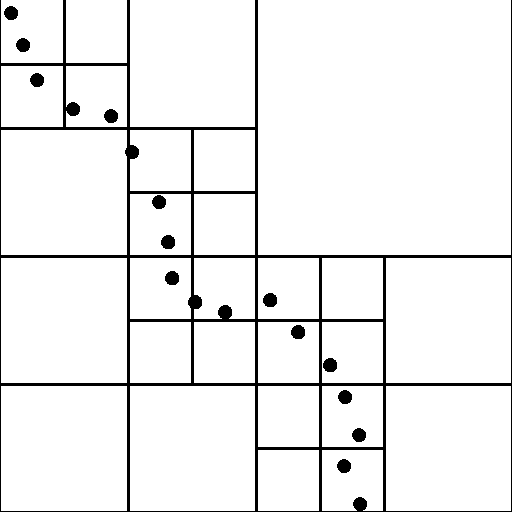
Let n be the octree height. With similarity transformation put all
allowed camera locations. A possible way out is to use
the points into the cube with edge length equal to 2n. We’ll store
overlapping LDIs, or six LDI with common camera center [3], or
node of octree only if corresponding cube contains at least one
even special centers of LDI projection around the object [4].
point (Figure1). Set the node color equal to arithmetical mean of
Introduction of the hierarchical approach to IBR such as LDI Tree
colors of points contained in corresponding cube.
[5], QSplats [6], Hierarchical Image-based Rendering [7] allows
to easily determining Level Of Detail (LOD).
The last years saw a lot of interest to joint usage of volumetric
textures and polygonal rendering. The main disadvantage of such
structures in increasing size of storage, growing like n . One of solutions to this problem is a set of bounding boxes with small 3D textures in each [8].
3. RENDERING 3.1 Recursive transform computation
Detailed description of hierarchical transformation computation and back-to-front display order algorithm based on octree
coordinates decomposition was described in object-order
volumetric rendering techniques [9,10]. This process makes
Figure 1. BVO approximation of points with n=0,1,2,3 (2D
modification because of specialized BVO representation.
Let n be octree height, T - transformation matrix 4x4, v - normal
2.2 Approximation of LDI and Multiple
coordinates of voxel. Assume that voxel coordinates are stored (as noticed in introduction) in packed implicit form, and rewrite node
Depth Images
coordinate as (1) and node transformation as (2).
Each of these structures can be represented as a set of 3D colored
points in unified orthogonal coordinate system and converted to
2.3 Approximation of Polygonal Model
Put all vertexes into a bounding cube. Represent all polygons as
set of triangles. We’ll recursively split each of the triangles into
four similar triangles, and continue doing so while there exist a
triangle with side whose length is greater than one. Treating all
the obtained vertices as color points we create binary volumetric octree like in 2.1.
Let f be any term in the sum (2). With fixed T it can be computed at frame preprocessing step in a table look-up fashion (3).
2.4 Continuity preservation condition
Condition of continuous visualization of voxels is ‘continuity’ of
nearby voxels visualization. Two voxels are called neighbours if their edges have common point. Hence, every voxel (except
Rewrite objective function in convenient for the recursive
extremes) has 26 neighbours. Let us examine how this condition
is mapped on continuity of source representation.
2.4.1 Multiple depth images
The source of depth image can be of different nature: real photos
with laser distance map, ray-casting of volumetric model, ray-
tracing of polygonal model, z-buffer with image, etc. We’ll
Tv = F (σ , F (σ .F (σ ).))
examine only the case of visualization of Lambert opacity surface
Compare number of operations for hierarchical warping
fragment from several cameras in orthogonal projection.
transform computation (4) and for equivalent direct 3D
Sufficient condition of continuity preservation of surface
warping in parallel projection case (Table 1). For these
fragment. All three conditions must be satisfied:
purpose we need to roughly calculate number of nodes in
1) The fragment is completely visible by one of the
BVO. Let p be the number of opacity cubes on n-th 3D
mipmap level. Because we use method of surface
2) The angle between this camera view direction and
approximation, p is directly proportionate to the area of
surface normal at every point of the surface
approximated surface, therefore p ~ n . Hence the total
3) Pixel side length in depth image resolution
corresponding to this camera does not exceed
For comparison let us assume that p = kn , where coefficient k
Necessary condition: the fragment is visible from one of
depends on model and typically is in range 0.5<k<2.
2.4.2 Opacity polygonal model Table 1. Computation cost of normal coordinates transformation
From the algorithm 2.3 it follows that if two polygons are
continuously connected, then corresponding volumes are
connected through neigh-boring voxels. The opposite is not true: two unconnected triangles that are closer to each other than voxel
edge length will be joined into neighbours voxels.
3.2 Pre-Warping
The basic IBR problem occurs at resampling step and is called gap-filling problem. There exist two base methods for solving this problem: linear interpolation between points (used in RT) and splatting (most LDI based methods, QSplats). In our approach, we used splats because of its predetermined size. The size of splat in volumetric based rendering must be sufficient to cover the corresponding volume. This size depends on linear sizes of voxel
and pixel. Let VPP = voxel edge/pixel size. The splats also differ
in type of kernel. The complex high quality splats are used, in
Figure 2. Integrating BVO model into a scene
Volumetric Rendering most with Gaussian kernel [11], in Point
Rendering systems they are ellipses [6] and in IBR methods mesh-splats are frequently used [12]. However, these splats require the
4. RESULTS AND CONCLUSION
large amount of computation. Using simple splats like small single-color opacity boxes leads to aliasing, noticeable at model
We would like to demonstrate speed and rendering quality of
borders and time-aliasing, noticeable when the viewing position
three models obtained from IBR-representations.
slightly changes. These artifacts can be suppressed by using subpixel level. Let SPL subpixel level. Let us analyze conditions
The first two models were obtained from orthogonal LDI, and the
last one – from six images with depth. Tests were run on Intel Celeron 500MHz. Table 2 shows frame rates with different 3D
splatsize ≥ L(ϕ,ψ )VPP SPLSPL
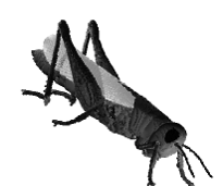
mipmap level and different Sampling Modes (see section 3.2). The
tests are illustrated in Figure 3 and Figure 4.
Here L is the length of voxel diagonal projection and depends on
Table 2. Software rendering times for different sampling
the angle at which the voxel is viewed. As discussed in the
Introduction, the best quality/speed ratio is achieved when volume
edge size ≈ pixel edge size i.e. VPP ≈ 1. Imposing also a
condition that the splat size must be identical for all volume
resolutions, we have only two sampling methods satisfying these
Sampling mode 1: SPL=1, splat 2x2, 0.57<VPP ≤ 1.14
• Sampling mode 2: SPL=2, splat 3x3, 0.44<VPP ≤ 0.88
The difference in speed and quality of these rendering methods is
Grasshopper 3.3 Post-Warping
Unlike RT method, the Post-Warping procedure is needed mostly
to provide compatibility of BVO representation with other IBR or Polygonal models in common scene.
For this purpose, a square texture is introduced into the scene, lying between the camera and BVO object. This texture plane must be parallel to the camera screen (Figure 2). The binary logarithm of the side of this textured square is equal to the maximum number of levels-of-detail (“3D mipmapping levels”) used in pre-warping step.
For smooth change between LODs, we do not use standard 2D-mipmaps for trilinear filtering, but projections of 3D-mipmaps
instead (see the visual difference between 2D and 3D mipmaps in Figure 5).
Figure 3. Successive 3D mipmaps (8-th, 7-th, 6-th)
[4] Rademacher, Paul and Gary. Multiple-Center-of-Projection Images. SIGGRAPH’98.
[5] Chun-Fa Chang, Gary Bishop, Anselmo Lastra. LDI Tree: A Hierarchical Representation or Image-Based Rendering. SIGGRAPH’99.
[6] Szymon Rusinkiewicz, Marc Levoy. QSplat: A Multiresolution Point Rendering System for Large Meshes. SIGGRAPH 2000.
[7] Hierarchical Image-Based Rendering using Texture Mapping Hardware. Proceedings of the Eurographics Workshop on Figure 4. Different sampling modes
[8] Rüdiger Westermann, Ove Sommer, Thomas Etrl.
Decoupling Polygon Rendering from Geometry using
Apart from using for IBR, BVO structure can be also used in
Rasterization Hardware. Rendering Techniques ’99
hardware-accelerated polygonal rendering. It can achieve the greatest efficiency by replacing polygonal models at long
[9] A. Li and G. Crebbin. Octree Encoding of Objects from
distances, where triangle sizes becomes comparable with pixel
Range Images. Pattern Recogniton 1994.
[10] Frieder G., Gordon D. and Reinolds. Back-to-Front Display of Voxel-Based Objects. IEEE Computer Graphics and 5. ACKNOWLEDGMENTS
[11] L. Westover. Footprint evaluation for volume rendering.
Samsung Advanced Institute of Technology (SAIT) was
supported this research under the “Advanced 3D Rendering Technology” project. I wish to express my gratitude to Yuri
[12] William R. Mark, Leonard McMillan, Gary Bishop. Post-
Bayakovski and Leonid Levkovich-Maslyuk for helpful
Rendering 3D Warping. Symposium on Interactive 3D About the author 6. REFERENCES
Alexander Zhirkov is a graduate student of Computational
[1] Manuel M. Oliveira, Gary Bishop, McAllister. Relief
E-mail: [email protected]
[2] Steven Gortler, Li-wei He, Richard Szeliski. SIGGRAPH ‘98
[3] Manuel M. Oliveira, Gary Bishop. Image-Based Objects.SIGGRAPH ‘99.
Blackwell Science, LtdOxford, UKBJUBJU International1464-4096BJU InternationalMay 2004937A little more than 10 years has passed since TRAINING AND MENTORING IN UROLOGY: THE ‘LAP’ GENERATION Clayman and Kavoussi performed the first S.V. BARIOL and D.A. TOLLEY – Scottish Lithotriptor Centre, Western General Hospital, techniques have flourished in the few units dedicated to laparosc
UMaT Second Congregation Address Delivered by the Vice Chancellor Professor D. Mireku-Gyimah Honourable Minister of Lands and Natural Resources representing His Excellency, the President of the Republic of Ghana Honourable Ministers of State and Members of Parliament Chairman and Members of the University Council My Colleague Vice Chancellors of Sister Universities Pro Vice Chancellor and


 3. RENDERING
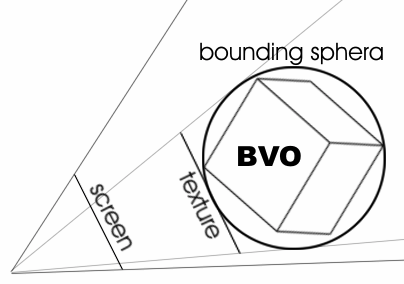


 3.2 Pre-Warping
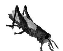
 [4] Rademacher, Paul and Gary. Multiple-Center-of-Projection Images. SIGGRAPH’98.
[5] Chun-Fa Chang, Gary Bishop, Anselmo Lastra. LDI Tree: A Hierarchical Representation or Image-Based Rendering. SIGGRAPH’99.
[6] Szymon Rusinkiewicz, Marc Levoy. QSplat: A Multiresolution Point Rendering System for Large Meshes. SIGGRAPH 2000.
[7] Hierarchical Image-Based Rendering using Texture Mapping Hardware. Proceedings of the Eurographics Workshop on
Figure 4. Different sampling modes
[4] Rademacher, Paul and Gary. Multiple-Center-of-Projection Images. SIGGRAPH’98.
[5] Chun-Fa Chang, Gary Bishop, Anselmo Lastra. LDI Tree: A Hierarchical Representation or Image-Based Rendering. SIGGRAPH’99.
[6] Szymon Rusinkiewicz, Marc Levoy. QSplat: A Multiresolution Point Rendering System for Large Meshes. SIGGRAPH 2000.
[7] Hierarchical Image-Based Rendering using Texture Mapping Hardware. Proceedings of the Eurographics Workshop on
Figure 4. Different sampling modes